Most digital cameras today use a single CCD or CMOS sensor. To capture color information, a color filter array (CFA) is placed in front of the sensor. This array, usually composed of three filters, limits the sensitivity of each photocell to one part of the visible spectrum. Consequently, each pixel of the CFA image only contains information about this limited range, i.e. one color response. However, three colors per pixels are needed to render images on a particular display device. An algorithm called color demosaicing is therefore applied to regenerate the missing colors.

|
| Figure 1: A typical CFA array (Bayer CFA). There are two times more green pixels than red and blue. |
In a CFA image, spatial and chromatic information are mixed together, as only one color sensitivity is available at each pixel. For this reason, demosaicing will always involve a trade-off between spatial resolution reconstruction and color rendering.
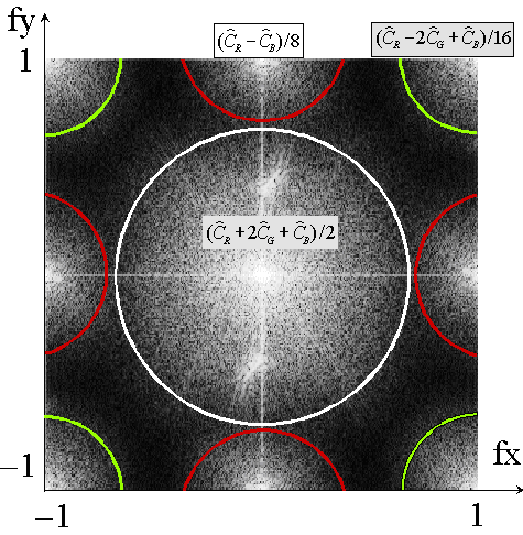
The arrangement of color filters in a CFA is usually regular. Due to this periodicity, luminance and opponent chromatic signals have specific locations in the spatial Fourier domain. Moreover, luminance can be defined in such a way that it has maximum spatial resolution, whereas opponent chromatic signals are sub-sampled [1].
 |
 |
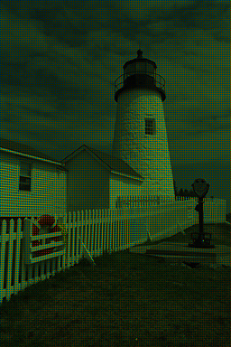
| Figure 2: A CFA image and its Fourier spectrum. Luminance is located in the middle, where as chrominance is located on the sides and the corners. | |
Such a CFA image model has several advantages when considering demosaicing. It is possible to design a demosaicing algorithm by selecting frequencies corresponding to luminance and opponent chromatic signals. The three-color per pixel image is reconstructed as the sum of estimated luminance and interpolated chrominance [2]. The estimators can be designed as uniform linear convolution filters [3], as the frequencies of luminance and opponent chromatic signals are localized in the Fourier domain, and the localization depends only on the arrangement of the color filters in the CFA. Since luminance is defined with maximum resolution, it is not subject to interpolation and thus is able to preserve spatial information. We found that our demosaicing algorithm, compared to other approaches, gives excellent results at low computational complexity [2,3].
Luminance and opponent chromatic signals share the same two-dimensional Fourier space for their representation. Artifacts may result in the demosaiced image if their representations overlap (alias). Using the Fourier representation, we can clearly explain the different artifacts that can occur in demosaicing as aliasing between luminance and chrominance, and under- or overestimating luminance and chrominance [2,3].
There are four visible artifacts: excessive blurring, grid effect, water color, and false color. Actually, blurring is not directly an artifact related to aliasing. Rather, it occurs when we choose a narrower luminance filter in order to prevent having chrominance information in the luminance. Choosing a larger filter can result in a grid effect especially visible in flat (homogeneous) regions of the image, due to the high frequency content of the chrominance signal spilling into luminance. The same applies for chrominance. False color appears due to high luminance frequencies in the chrominance signal when the high-pass filter is too large. When the filter is too small, a "watercolor" effect might appear as colors go beyond the edges of an object. For classical demosaicing algorithms, the two most visible effects are blurring and false color.
We found several ways to improve the demosaicing results. A better separation, and therefore a better reconstruction, is given by using a CFA that contains twice more blue filters than red and green [3]. The chrominance spectra in the middle of the sides (R-B) changes to (R-G). Considering that the red and green channels are usually more correlated in terms of spectral information, the area covered by the chrominance spectra is decreased [4], allowing for a better luminance estimation. We also found that in general, increasing the correlation between the color filter sensitivities has an influence on demosaicing. Having a larger correlation between the color channels increases the quality of reconstruction (in the extreme, the three filters are equal, resulting in a greyscale image), but decreases the color rendering ability [4]. However, for any camera design and color rendering intent, optimal color sensitivities can be found.
 |
 |
 |
 |
| Figure 3: The four visible artifacts that can occur after demosaicing. (a) Excessive blurring (b) Grid effect (c) Water color (d) False color | |
David Alleysson
Jeanny
Hérault
Joanna Marguier